The 2nd installment in my “one-day” hacks, I present a simple desk clock. You may recall a prior version of this, which I severely overcomplicated from the technical end for unclear reasons. This version is much simpler, and was designed (but not fully printed) in one day.
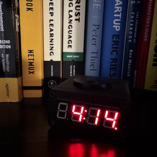
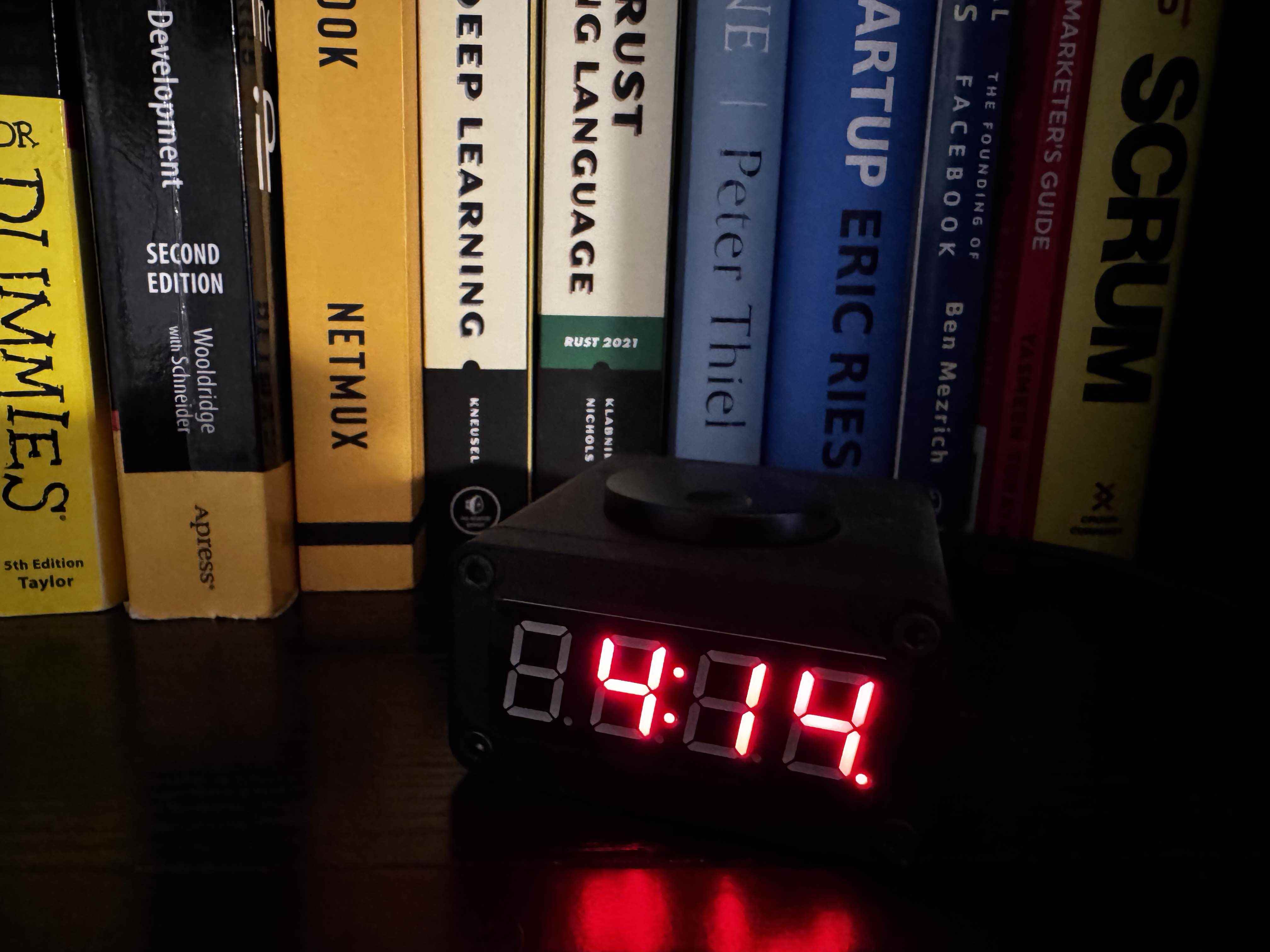
Final Product
Parts List
Some of these, I had but a few (like the encoder, etc) - I purchased with the general intention of using it for this project.
- KB2040 (Adafruit)
- I2C RTC (Adafruit)
- Piezo Buzzer (Adafruit)
- I2C 7-segment display (Adafruit) (color of your choice)
- I2C Encoder (Adafruit)
- Scrubber Knob 35mm (Adafruit)
- StemmaQt/Qwiic Jumpers
- Rubber feet
- 4x M3x6 screws
- 4x M3x12 screws
- 4x M3x10 threaded inserts
- Black Nylon m2.5 standoffs Any m2.5 will work, but this kit contains all that’s needed
- M2.5 screws
- 4x M2.5x8mm standoff (both ends tapped for screws, holds encoder in)
- 2x M2.5x10mm standoff (both ends tapped for screws, holds RTC module)
Software
First, given that all the core components can be easily plugged without wires - I plugged them together and started hacking on software for it.
I started with the following screens - to be actuated when you scroll the rotary encoder:
- Clock Screen (default - and resets after 10s of non-interaction)
- Year
- Month
- Day
- Settings - 24hr / 12hr
- Settings - Screen Brightness
- Settings - Alarm Status (on/off)
- Settings - Alarm Time
When you press and hold on any screen - it activates editing mode. Clicking saves the current setting (usually indicated by flashing numbers).
The code, is currently hosted in this repo: https://github.com/richinfante/rp2040-alarm-clock. I needed to copy a few modules from the CircuitPython Bundle to support the encoders, display, etc.
Enclosure
For design aesthetics - I wanted something minimal, as few buttons as possible. And, something that seemed kind of rugged. But - if you decided to print it in any other color besides black, it would work.
Also, as with many of my projects - tried to design this so that you could print it without supports, flat on the print bed. For mine, I used my favorite Overture black matte PLA.
It’s split into three pieces:
- Front
- Back
- Main Housing
There are extra mounting holes for future use - right now, the KB2040 sits in place so it won’t move with the piezo speaker pressure fit into the housing. I might change this out in the future.
Assembly
- Insert the 7 Segment into the front cover, securing it with 4 M2 screws.
- Install the heat-set M3x10 thread inserts into the main body.
- Install the standoffs on rotary encoder, and secure to the bottom of case.
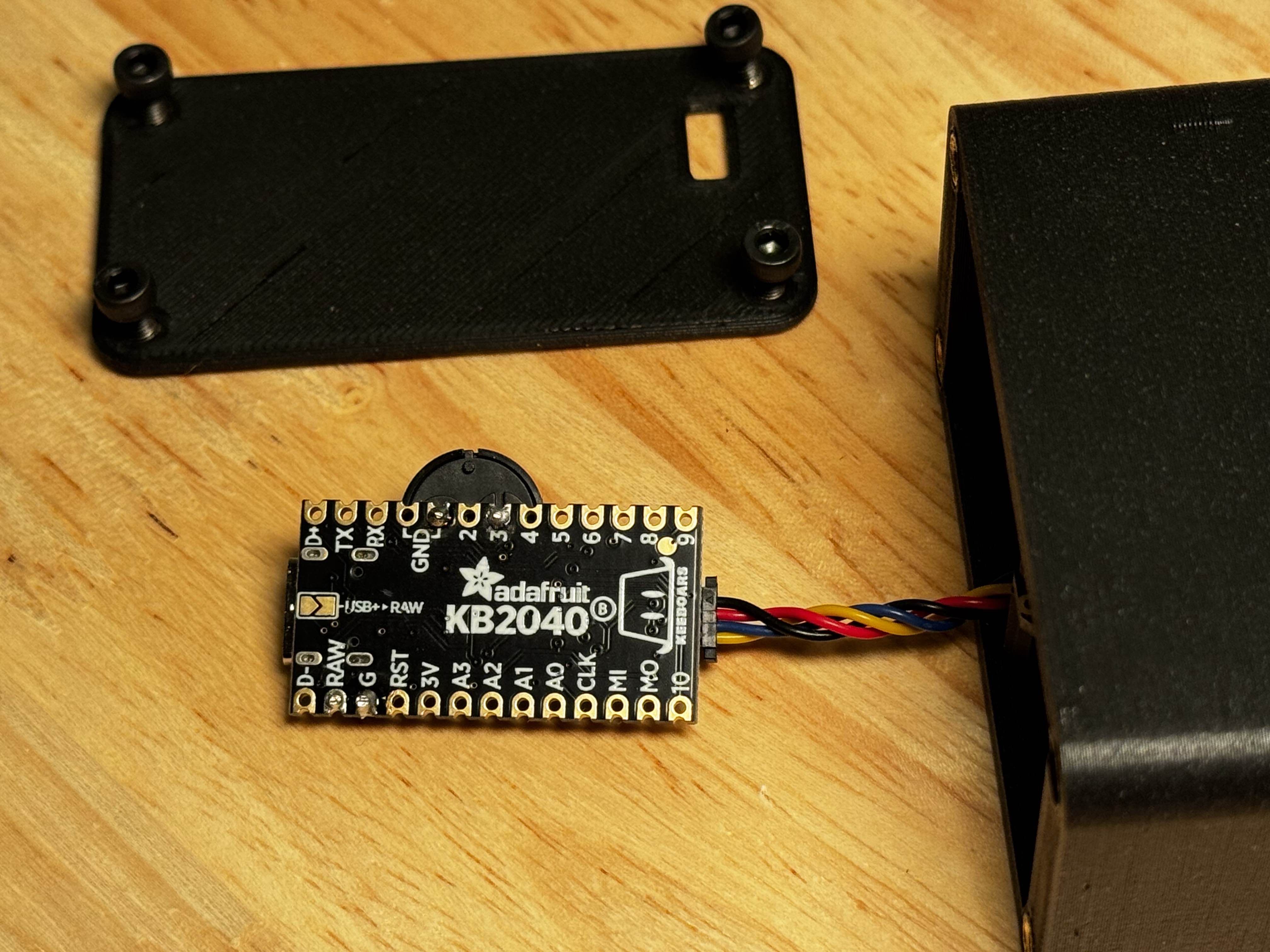
- Install stemma Qt wire to on the KB2040 the KB2040 and mounting bracket.
- Install stemma QT wite from the KB2040 to the side of the screen. Wire the other side of the kb2040 to the rotary encoder, and then from the rotary encoder to the RTC.
- Install the RTC
- Install the back plate.
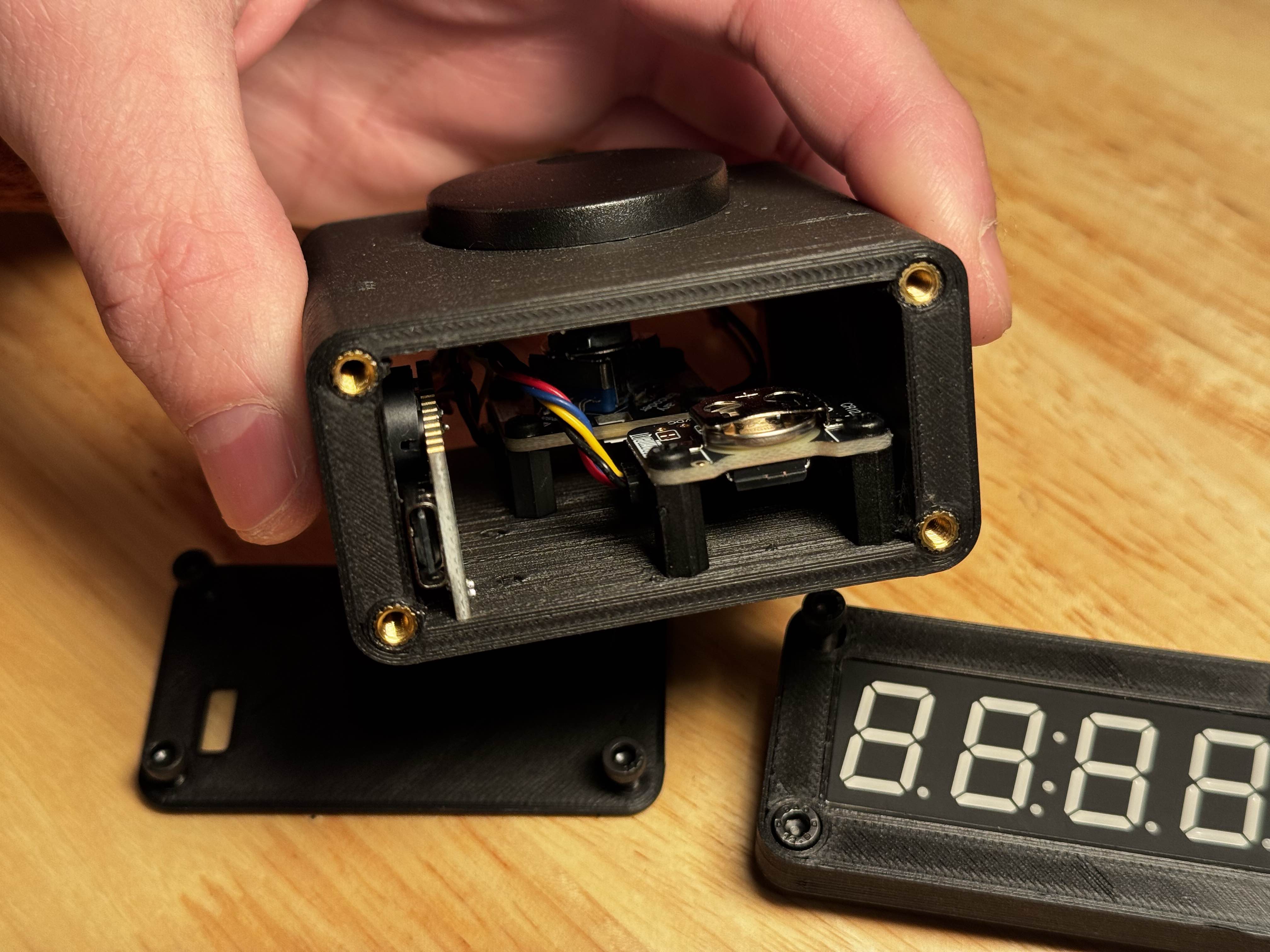
Rear View
Rear view with cover off
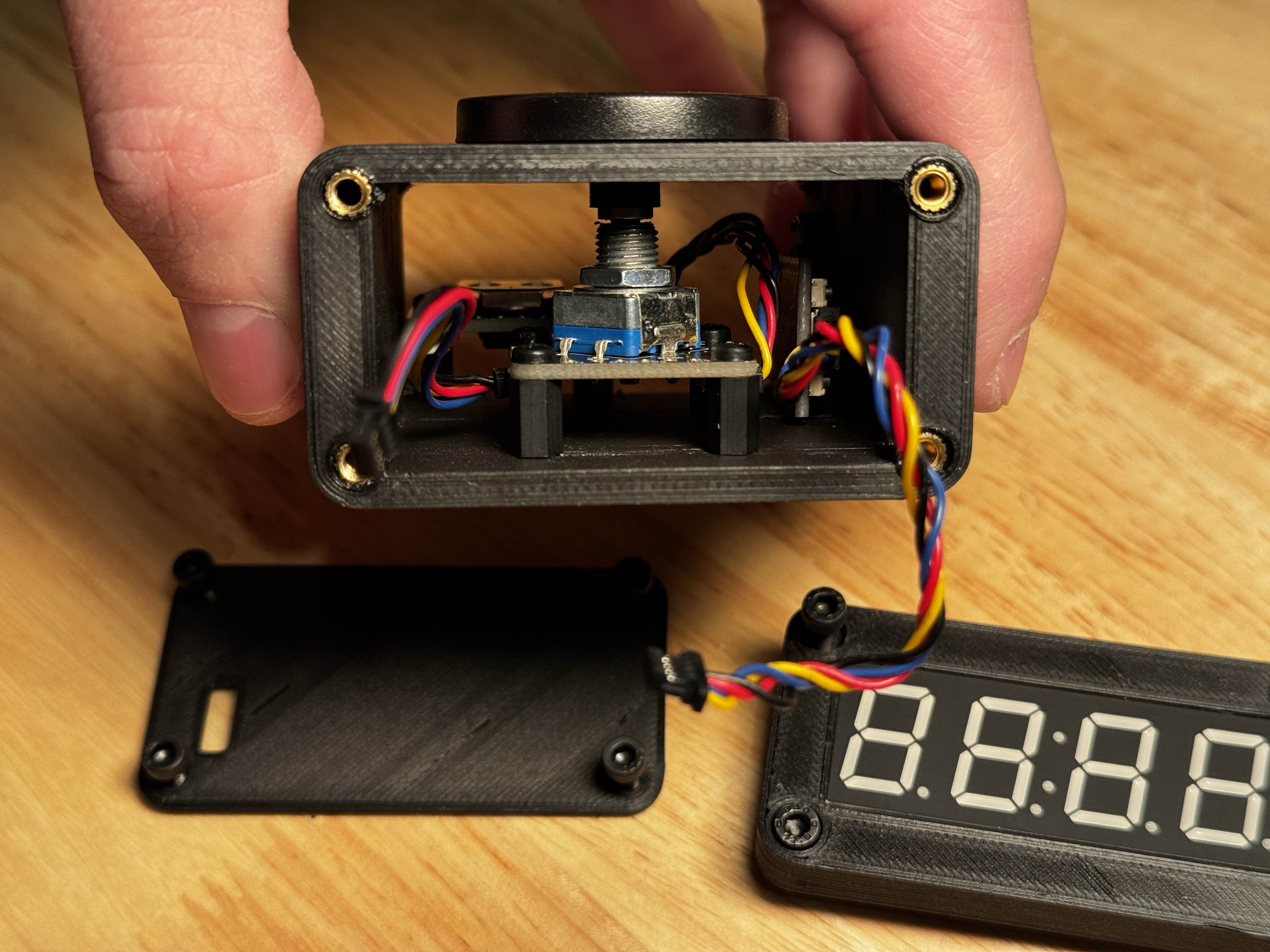
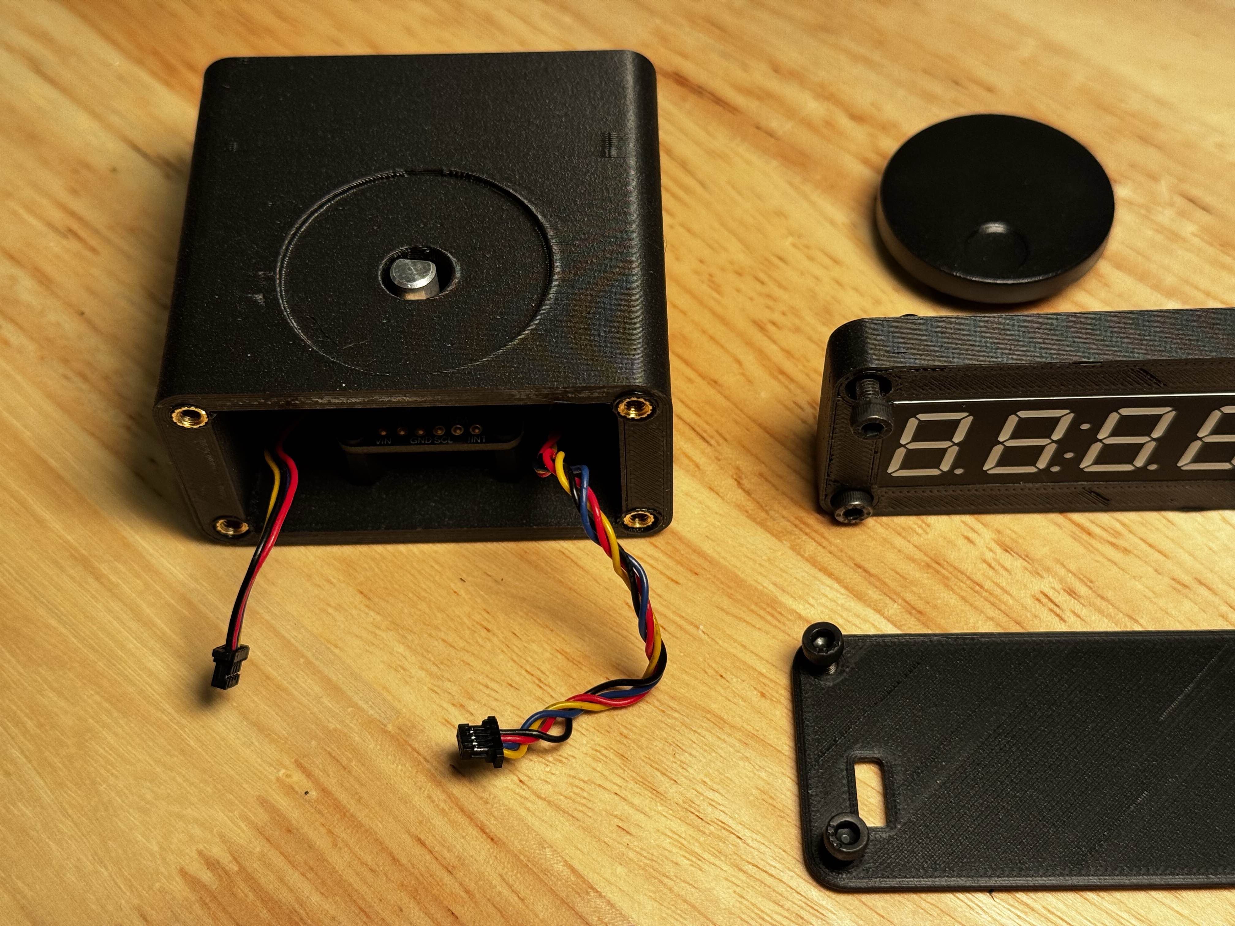
Front View
Front view with front plate/display off. Note the two Stemma QT wires that plug into the display.
Top View
Top view with all plates off. Note the front with Stemma QT wires for the screen.
Buzzer
I soldered the piezo buzzer onto the one of the grounds and into digital out #3. I originally was planning on doing 5V DC in using the RAW/GND pins on the other side - so remnants of that are also present, but aren’t needed!
Profit
Here’s what it looks like, assembled and running! Rotating the top encoder cycles through the screens, and the end!
I posted a demo on my Youtube channel, click to watch